Publication
Mueller, S., Lopes, P. and Baudisch, P.
Interactive Construction: Interactive Fabrication of Functional Mechanical Devices.
In Proceedings of
UIST ’12
, pp. 599-606.
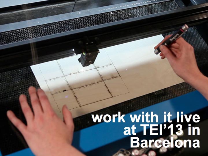
Demo at CHI'13, Demo at TEI'13, Talk at SIGGRAPH'13
DOI
Paper
Video
Slides
Talk
I worked on this project before joining MIT. Here is the original constructable project page at Hasso Plattner Institut.
 Sponsors
 Press
Video
Talk
Slides
Press
Video
Talk
Slides


I worked on this project before joining MIT. Here is the original constructable project page at Hasso Plattner Institut.
1 / 74

2 / 74

3 / 74
4 / 74

5 / 74
6 / 74

7 / 74
8 / 74
9 / 74
10 / 74
11 / 74
12 / 74
13 / 74
14 / 74

15 / 74
16 / 74

17 / 74
18 / 74
19 / 74

20 / 74
21 / 74
22 / 74
23 / 74
24 / 74
25 / 74

26 / 74
27 / 74

28 / 74

29 / 74
30 / 74

31 / 74
32 / 74
33 / 74

34 / 74

35 / 74
36 / 74
37 / 74
38 / 74
39 / 74
40 / 74
41 / 74
42 / 74

43 / 74
44 / 74
45 / 74

46 / 74

47 / 74

48 / 74
49 / 74
50 / 74
51 / 74
52 / 74

53 / 74

54 / 74

55 / 74
56 / 74
57 / 74
58 / 74
59 / 74

60 / 74
61 / 74

62 / 74
63 / 74
64 / 74
65 / 74
66 / 74
67 / 74
68 / 74
69 / 74
70 / 74

71 / 74
72 / 74
73 / 74
74 / 74

Interactive Construction:
Interactive Fabrication of Functional Mechanical Devices
 Figure 1: (a) Constructable users interact by drafting directly on the workpiece with hand-held lasers. (b) Here the user sketches a finger joint across two objects (c) The system responds by cutting the desired joint using the cutting laser. (d) Constructable allows creating precise and functional mechanical objects, such as this simple motorized vehicle.
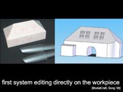
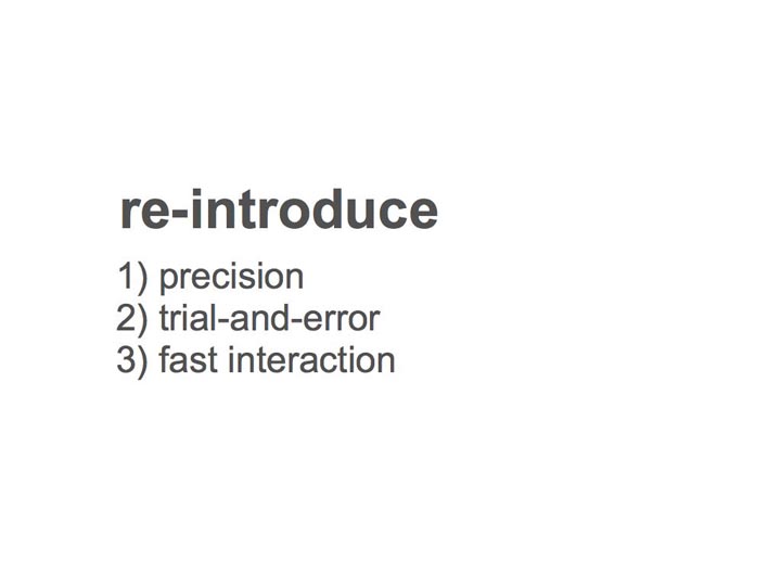
Personal fabrication tools, such as laser cutters and 3D printers allow users to create precise objects quickly. However, working through a CAD system removes users from the workpiece. Recent interactive fabrication tools reintroduce this directness, but at the expense of precision.
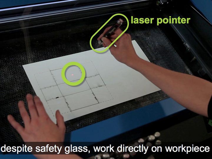
In this paper, we introduce constructable, an interactive drafting table that produces precise physical output in every step. Users interact by drafting directly on the workpiece using a hand-held laser pointer. The system tracks the pointer, beautifies its path, and implements its effect by cutting the workpiece using a fast high-powered laser cutter.
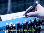
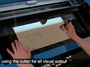
Constructable achieves precision through tool-specific constraints, user-defined sketch lines, and by using the laser cutter itself for all visual feedback, rather than using a screen or projection. We demonstrate how Constructable allows creating simple but functional devices, including a simple gearbox, that cannot be created with traditional interactive fabrication tools.
Introduction
Rapid prototyping/personal fabrication tools, such as 3D printers and computer controlled milling machines help users create one-off prototypes rapidly.
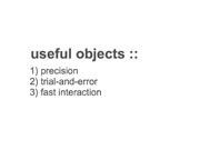
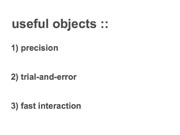
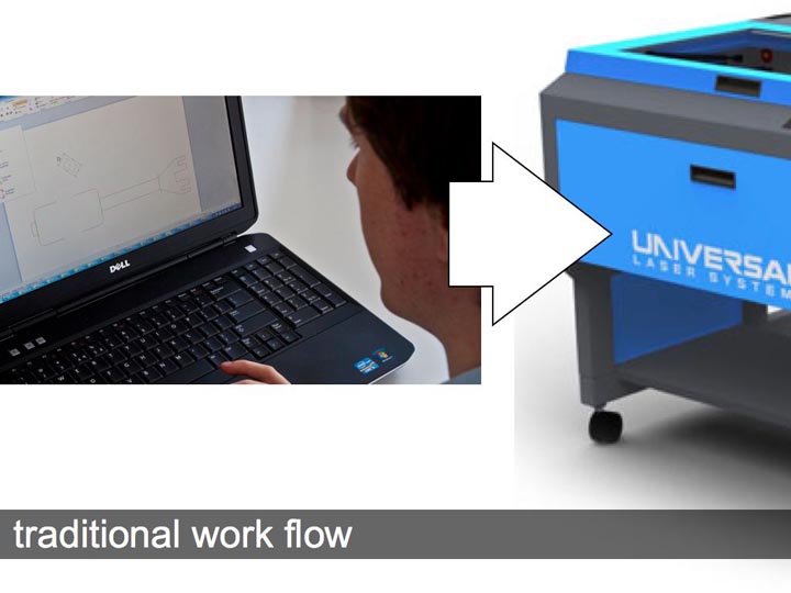
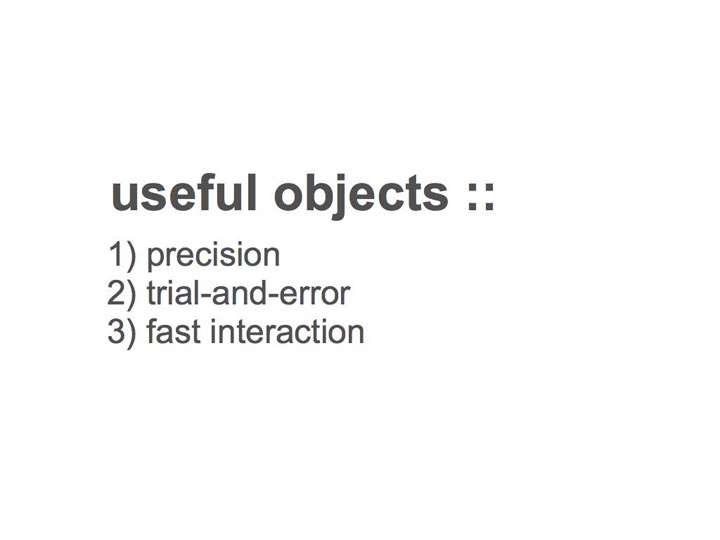
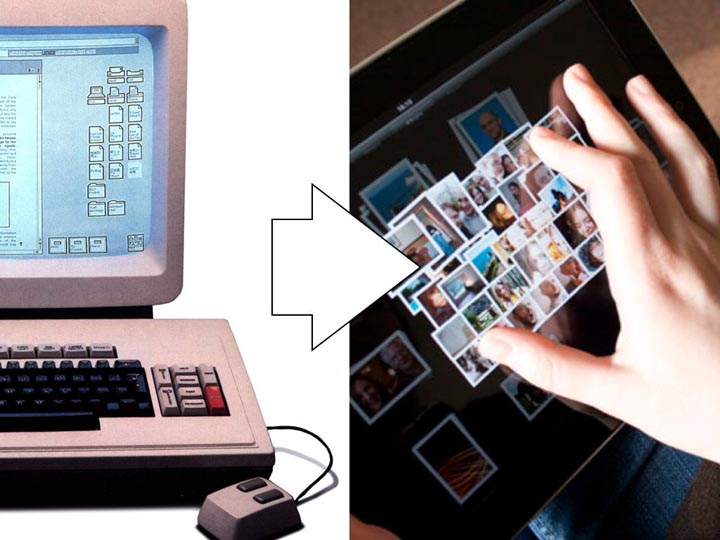
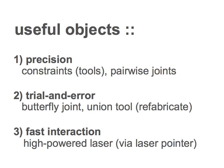
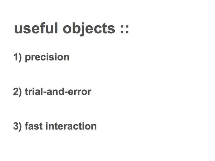
The process places CAD software at the frontend to personal fabrication tools. The use of CAD provides three main benefits over traditional woodworking tools, such as saws and wood chisels: (1) Fast interaction, it is generally faster to describe what to do to a software program than to operate an actual mechanical tool. (2) Trial-and-error: Users can undo mistakes and even selectively correct flaws. (3) Precision: constructions aids, such as constraints allow users to precisely manufacture pieces that can perform mechanical functions.
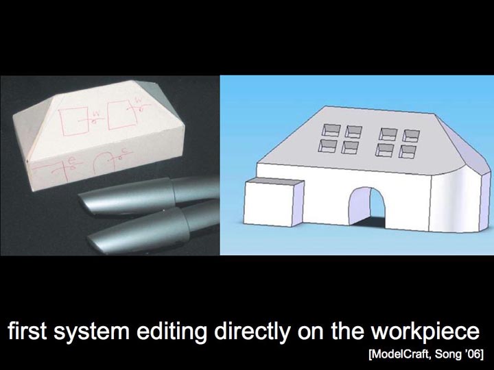
On the flipside, the transition from traditional tools to personal fabrication tools means that all editing is now done on a computer screen, which removes users from the workpiece and prevents users from refining their design interactively along the way [31].
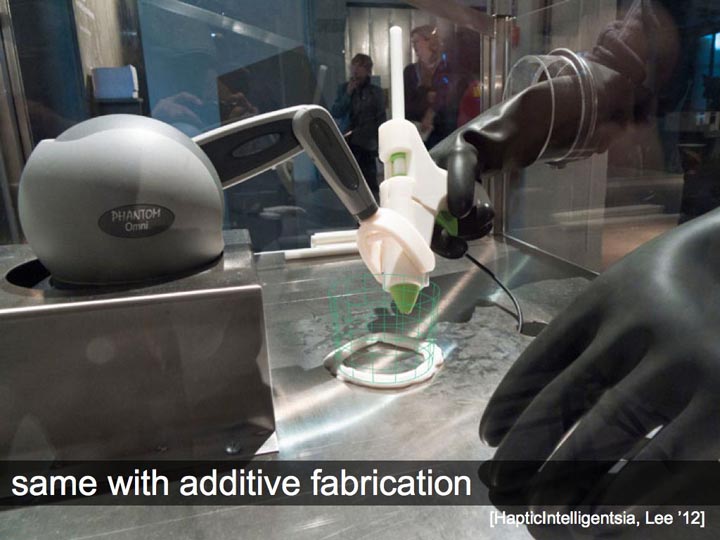
Interactive Fabrication
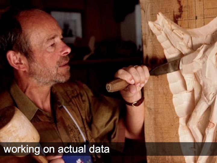
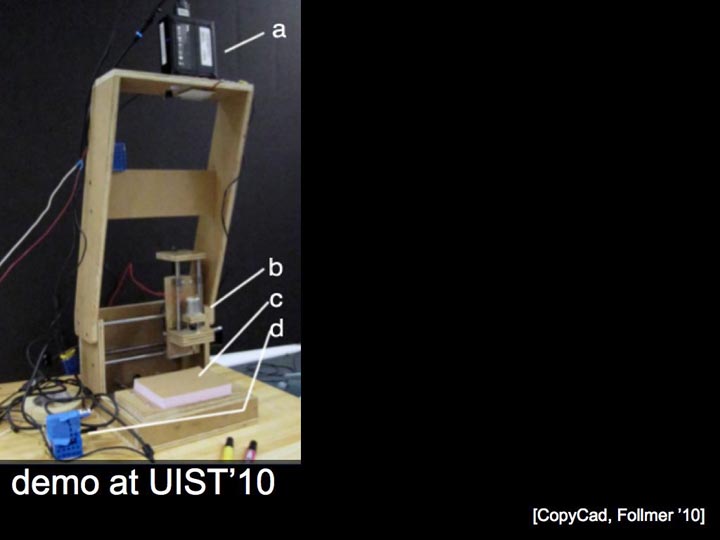
Interactive fabrication systems address this by letting users once again work directly with the workpiece [31]. CopyCAD [8], for example, allows users to draw on the workpiece.
A key element of interactive fabrication systems is that they provide output to users not at the end of the process, but after every editing step (e.g., Shaper [31]). This allows users to (1) validate their designs earlier and (2) build subsequent work steps on the result of earlier steps. The related work suggests that this offers value to artists and designers [31], as their creative process is often inspired by seeing the partially completed workpiece. We argue that similar benefits can be achieved when working on technical projects.
The transition to interactive fabrication, however, comes at a cost. First, since editing is now intertwined with fabrication, editing becomes slower, because users have to repeatedly wait for the fabrication engine to finish. Second, as we give up on traditional tools like CAD, users lose the precision required to create functional devices.
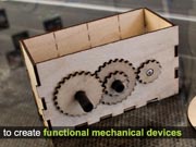
In this paper, we attempt to put these qualities back into interactive fabrication, moving it in the direction of what we call interactive construction. We present constructable, a laser cutter-based interactive construction system that allows users to construct functional mechanical devices, while maintaining the immediateness of an interactive fabrication system.
Constructable
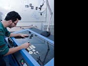
Constructable is a drafting table that produces physical output in every step. As illustrated by Figure 1, all interaction in constructable takes place on the workpiece, mediated through low-power hand-held laser pointers, which we call proxy lasers or simply tools. In the shown example, the user uses the finger joint tool to add finger joints between two pieces by crossing the two involved edges.
Proxy lasers are too weak to affect the work piece. To make the interaction ‘real’, constructable tracks proxy laser interactions using a camera mounted above (Figure 1b), reconstructs the tool’s path, transforms it using a constraint set defined by the current tool, and implements the effect using its high-powered cutting laser (Figure 1c). Since all key elements were constructed in the context of constraints, we obtain fully functional mechanical devices, such as the simple motorized vehicle shown in Figure 1d.
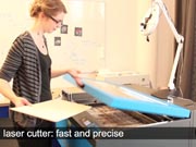
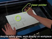
The combination of proxy laser and cutting laser is one of the key ideas behind our system, because it allows users to work faster and more interactively than the interactive fabrication systems in the related work. The reason is that the manipulation of materials that are durable enough for making functional mechanical devices requires a high-powered tool. These, however, require safety measures, such as our glass enclosure. Opening and closing the enclosure for each interaction takes too long, but by letting users point at the workpiece through the safety enclosure, constructable allows user’s attention to remain on the workpiece at all times, despite the enclosure. As intended, users witness how the workpiece changes with their every interaction first hand and not mediated by a screen or projector.
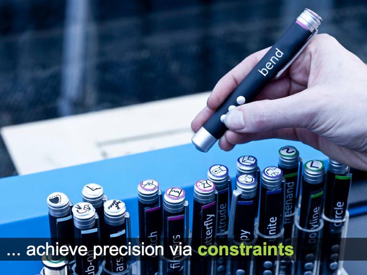
Constructable achieves its other main design objective, i.e., precision, using a system of constraints implemented by the individual proxy lasers.
Proxy lasers
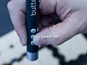
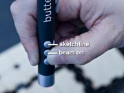
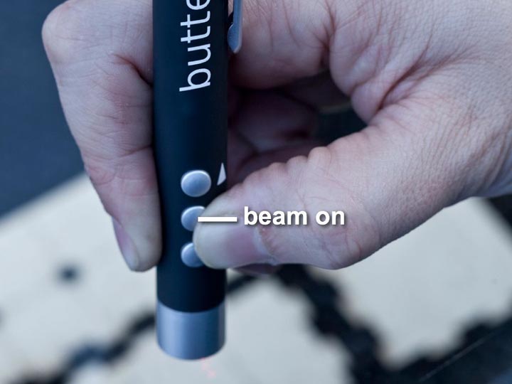
Figure 2 provides a closer look at the proxy lasers. Each proxy laser features three barrel buttons (Figure 2c). While held depressed, the middle button activates the beam, allowing the system and the user to see where the tool is pointed [21]. The visual feedback allows users to determine a starting point with precision before starting to cut. It thereby implements the tracking state of its three-state model [5].
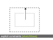
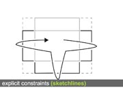
The other two buttons trigger the tool’s two modes of operation. The cut button allows cutting a tool-specific shape, such as a circle for the circle tool. The sketch line button creates the same shape, but etches it as a shallow dashed line into the surface of the material. Sketch lines have no direct impact on the mechanics of the workpiece, but instead serve as alignment aids that magnetically attract subsequent cuts (alignment lines [3]).
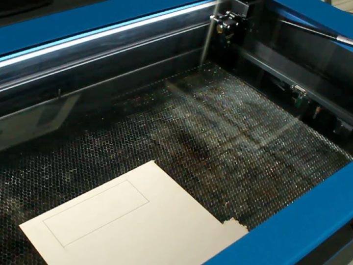
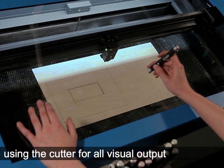
All tools explain themselves exclusively through the cut or sketch line they produce and there is no further visual feedback, i.e., no screen or projector. Since all output is created using the laser cutter itself, constructable’s geometry output is extremely precise.
Figure 1: (a) Constructable users interact by drafting directly on the workpiece with hand-held lasers. (b) Here the user sketches a finger joint across two objects (c) The system responds by cutting the desired joint using the cutting laser. (d) Constructable allows creating precise and functional mechanical objects, such as this simple motorized vehicle.
Personal fabrication tools, such as laser cutters and 3D printers allow users to create precise objects quickly. However, working through a CAD system removes users from the workpiece. Recent interactive fabrication tools reintroduce this directness, but at the expense of precision.
In this paper, we introduce constructable, an interactive drafting table that produces precise physical output in every step. Users interact by drafting directly on the workpiece using a hand-held laser pointer. The system tracks the pointer, beautifies its path, and implements its effect by cutting the workpiece using a fast high-powered laser cutter.
Constructable achieves precision through tool-specific constraints, user-defined sketch lines, and by using the laser cutter itself for all visual feedback, rather than using a screen or projection. We demonstrate how Constructable allows creating simple but functional devices, including a simple gearbox, that cannot be created with traditional interactive fabrication tools.
Introduction
Rapid prototyping/personal fabrication tools, such as 3D printers and computer controlled milling machines help users create one-off prototypes rapidly.
The process places CAD software at the frontend to personal fabrication tools. The use of CAD provides three main benefits over traditional woodworking tools, such as saws and wood chisels: (1) Fast interaction, it is generally faster to describe what to do to a software program than to operate an actual mechanical tool. (2) Trial-and-error: Users can undo mistakes and even selectively correct flaws. (3) Precision: constructions aids, such as constraints allow users to precisely manufacture pieces that can perform mechanical functions.
On the flipside, the transition from traditional tools to personal fabrication tools means that all editing is now done on a computer screen, which removes users from the workpiece and prevents users from refining their design interactively along the way [31].
Interactive Fabrication
Interactive fabrication systems address this by letting users once again work directly with the workpiece [31]. CopyCAD [8], for example, allows users to draw on the workpiece.
A key element of interactive fabrication systems is that they provide output to users not at the end of the process, but after every editing step (e.g., Shaper [31]). This allows users to (1) validate their designs earlier and (2) build subsequent work steps on the result of earlier steps. The related work suggests that this offers value to artists and designers [31], as their creative process is often inspired by seeing the partially completed workpiece. We argue that similar benefits can be achieved when working on technical projects.
The transition to interactive fabrication, however, comes at a cost. First, since editing is now intertwined with fabrication, editing becomes slower, because users have to repeatedly wait for the fabrication engine to finish. Second, as we give up on traditional tools like CAD, users lose the precision required to create functional devices.
In this paper, we attempt to put these qualities back into interactive fabrication, moving it in the direction of what we call interactive construction. We present constructable, a laser cutter-based interactive construction system that allows users to construct functional mechanical devices, while maintaining the immediateness of an interactive fabrication system.
Constructable
Constructable is a drafting table that produces physical output in every step. As illustrated by Figure 1, all interaction in constructable takes place on the workpiece, mediated through low-power hand-held laser pointers, which we call proxy lasers or simply tools. In the shown example, the user uses the finger joint tool to add finger joints between two pieces by crossing the two involved edges.
Proxy lasers are too weak to affect the work piece. To make the interaction ‘real’, constructable tracks proxy laser interactions using a camera mounted above (Figure 1b), reconstructs the tool’s path, transforms it using a constraint set defined by the current tool, and implements the effect using its high-powered cutting laser (Figure 1c). Since all key elements were constructed in the context of constraints, we obtain fully functional mechanical devices, such as the simple motorized vehicle shown in Figure 1d.
The combination of proxy laser and cutting laser is one of the key ideas behind our system, because it allows users to work faster and more interactively than the interactive fabrication systems in the related work. The reason is that the manipulation of materials that are durable enough for making functional mechanical devices requires a high-powered tool. These, however, require safety measures, such as our glass enclosure. Opening and closing the enclosure for each interaction takes too long, but by letting users point at the workpiece through the safety enclosure, constructable allows user’s attention to remain on the workpiece at all times, despite the enclosure. As intended, users witness how the workpiece changes with their every interaction first hand and not mediated by a screen or projector.
Constructable achieves its other main design objective, i.e., precision, using a system of constraints implemented by the individual proxy lasers.
Proxy lasers
Figure 2 provides a closer look at the proxy lasers. Each proxy laser features three barrel buttons (Figure 2c). While held depressed, the middle button activates the beam, allowing the system and the user to see where the tool is pointed [21]. The visual feedback allows users to determine a starting point with precision before starting to cut. It thereby implements the tracking state of its three-state model [5].
The other two buttons trigger the tool’s two modes of operation. The cut button allows cutting a tool-specific shape, such as a circle for the circle tool. The sketch line button creates the same shape, but etches it as a shallow dashed line into the surface of the material. Sketch lines have no direct impact on the mechanics of the workpiece, but instead serve as alignment aids that magnetically attract subsequent cuts (alignment lines [3]).
All tools explain themselves exclusively through the cut or sketch line they produce and there is no further visual feedback, i.e., no screen or projector. Since all output is created using the laser cutter itself, constructable’s geometry output is extremely precise.
 Figure 2: (a, b) Constructable offers 15 different proxy lasers and an undo button. (c) Each proxy-laser offers three barrel buttons.
Creating, Selecting, copying, and pasting using tools
Constructable achieves precision by means of sketch lines and by implementing constraints into every proxy laser. Constraints differ between tools.
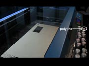
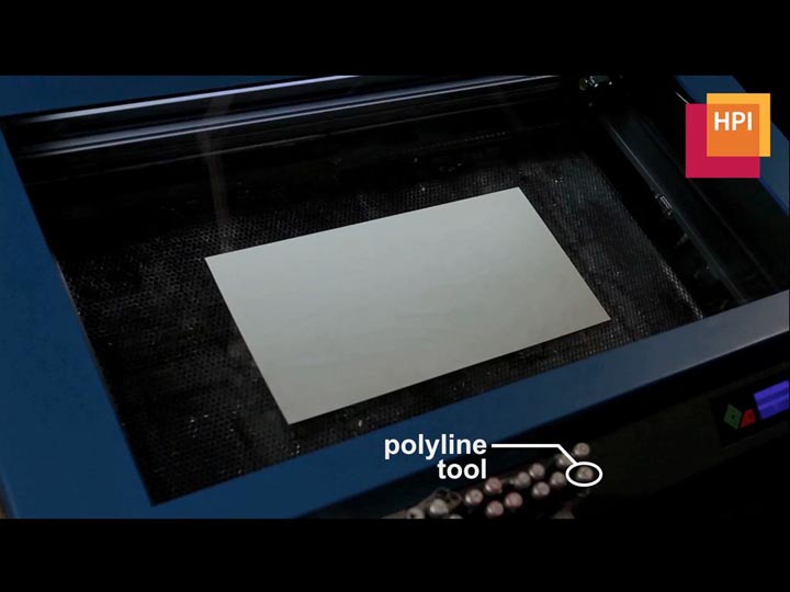
Creating: Polyline, Circle, and Freehand are constructable’s tools for creating objects from scratch. These tools are only moderately constrained. The circle tool, for example, always produces a perfect circle, but diameter and location remain freehand. The freehand tool is not subject to any constraints.
Most of constructable’s tools connect to or extend an existing object and this spatial relationship adds constraints. Users establish these constraints by selecting one or more existing objects. The finger joint tool, for example, snaps to existing lines.
Selecting: As illustrated by Figure 3, users select (a) a surface by clicking into it, (b) an edge by crossing it [2], and (c) a point by drawing a pigtail close to it [12]. We designed this selection mechanism so as to extend seamlessly to multiple objects. Users select (d) multiple surfaces by drawing a path across, (e) multiple edges by crossing multiple edges, and (f) multiple points as a sequence of multiple pigtails.
Figure 2: (a, b) Constructable offers 15 different proxy lasers and an undo button. (c) Each proxy-laser offers three barrel buttons.
Creating, Selecting, copying, and pasting using tools
Constructable achieves precision by means of sketch lines and by implementing constraints into every proxy laser. Constraints differ between tools.
Creating: Polyline, Circle, and Freehand are constructable’s tools for creating objects from scratch. These tools are only moderately constrained. The circle tool, for example, always produces a perfect circle, but diameter and location remain freehand. The freehand tool is not subject to any constraints.
Most of constructable’s tools connect to or extend an existing object and this spatial relationship adds constraints. Users establish these constraints by selecting one or more existing objects. The finger joint tool, for example, snaps to existing lines.
Selecting: As illustrated by Figure 3, users select (a) a surface by clicking into it, (b) an edge by crossing it [2], and (c) a point by drawing a pigtail close to it [12]. We designed this selection mechanism so as to extend seamlessly to multiple objects. Users select (d) multiple surfaces by drawing a path across, (e) multiple edges by crossing multiple edges, and (f) multiple points as a sequence of multiple pigtails.
 Figure 3: Constructable allows users to select (a) objects by pointing, (b) lines by crossing, and (c) points with pigtails. (d-f) To allow for fast selection, all selection gestures can be extended across multiple objects, lines, and points.
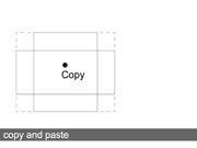
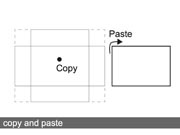
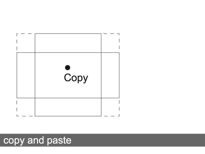
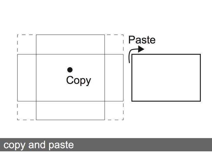
Pasting: A range of tools, such as the copy tool, results in the creation of new objects. The size and shape of a new object is determined implicitly, e.g., by the object being copied and does not require or allow for user input. However, to allow users to optimize material usage, we let users show constructable where to create it. As illustrated by Figure 4, users point constructable to available material by drawing a directional cropmark (see also [19]). The orientation of the cropmark specifies the orientation of the pasted object, allowing users to optimize for material use.
Figure 3: Constructable allows users to select (a) objects by pointing, (b) lines by crossing, and (c) points with pigtails. (d-f) To allow for fast selection, all selection gestures can be extended across multiple objects, lines, and points.
Pasting: A range of tools, such as the copy tool, results in the creation of new objects. The size and shape of a new object is determined implicitly, e.g., by the object being copied and does not require or allow for user input. However, to allow users to optimize material usage, we let users show constructable where to create it. As illustrated by Figure 4, users point constructable to available material by drawing a directional cropmark (see also [19]). The orientation of the cropmark specifies the orientation of the pasted object, allowing users to optimize for material use.
 Figure 4: Users paste an object by drawing a crop-mark. Constructable places the object into the “inside” of the cropmark. Cropmarks allow users to place objects carefully into available space while preventing them from cutting into adjacent contents.
Walkthrough: Constructing a Device
In the following, we illustrate constructable’s tools at the example of the simple motorized vehicle that we had briefly touched upon in Figure 1. Figure 5 shows the final outcome and the pieces required to produce it.
Figure 4: Users paste an object by drawing a crop-mark. Constructable places the object into the “inside” of the cropmark. Cropmarks allow users to place objects carefully into available space while preventing them from cutting into adjacent contents.
Walkthrough: Constructing a Device
In the following, we illustrate constructable’s tools at the example of the simple motorized vehicle that we had briefly touched upon in Figure 1. Figure 5 shows the final outcome and the pieces required to produce it.
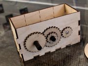
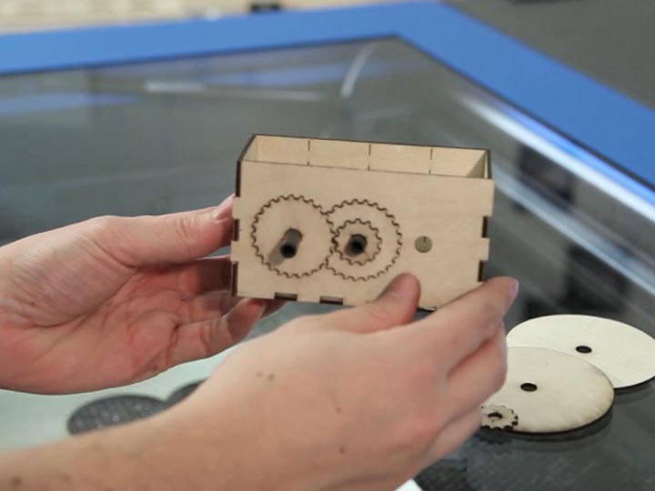
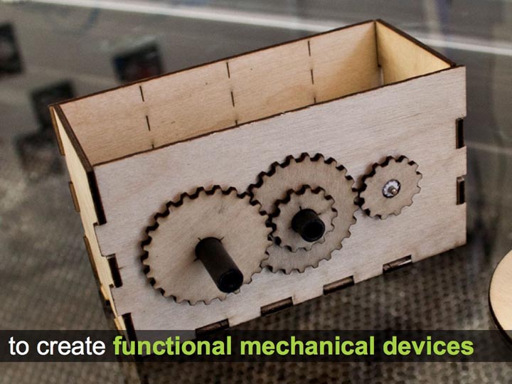
 Figure 5: (a-c) The gearbox in different states of assembly, for use in (d) a simple motorized vehicle.
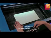
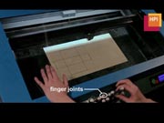
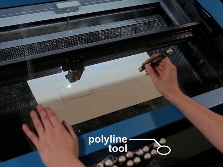
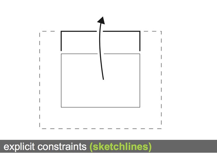
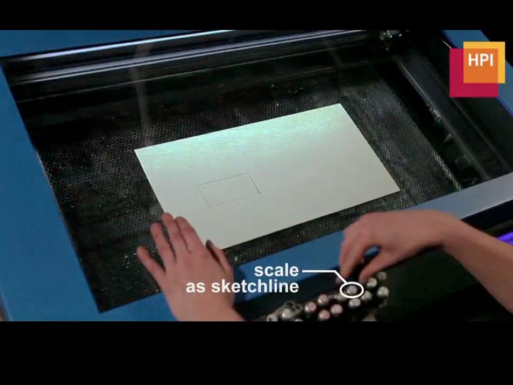
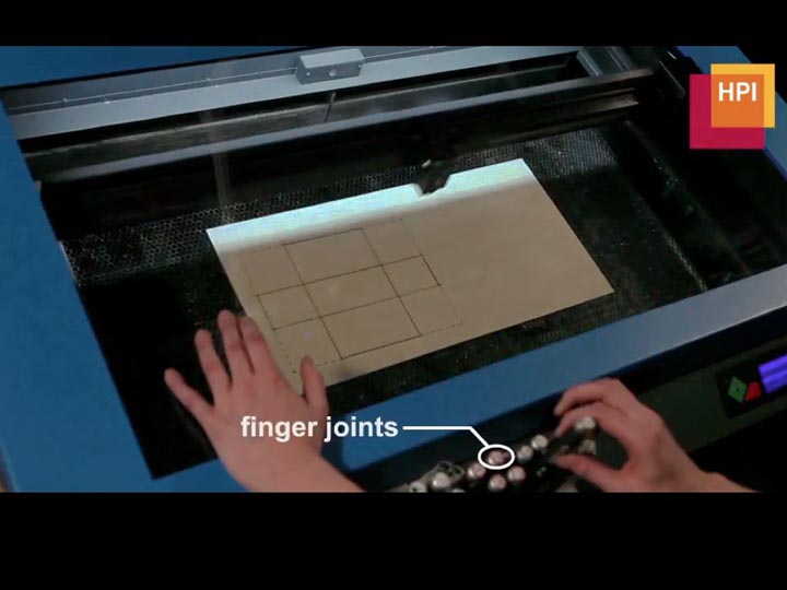
We start by creating the housing (Figure 6). (a) We use the polyline tool to sketch the rectangular base. (b) Using the sketch line button on the scale tool we create a sketch line rectangle around the base—this sets the height of the walls. (c) By crossing the north edge of the base with the Extrude tool, we create the first wall segment. (d) For efficiency, we create the remaining three walls using a single long stroke that extrudes the base east, south, and west. There is no limit on concatenating, so we could have also extruded all four walls in a single stroke. (e and f) To allow us to assemble the housing later, we add finger joints. We connect the walls by crossing pairs of respective edges using the finger joint tool. (g) Finally, we assemble the box by connecting the finger joints.
Figure 5: (a-c) The gearbox in different states of assembly, for use in (d) a simple motorized vehicle.
We start by creating the housing (Figure 6). (a) We use the polyline tool to sketch the rectangular base. (b) Using the sketch line button on the scale tool we create a sketch line rectangle around the base—this sets the height of the walls. (c) By crossing the north edge of the base with the Extrude tool, we create the first wall segment. (d) For efficiency, we create the remaining three walls using a single long stroke that extrudes the base east, south, and west. There is no limit on concatenating, so we could have also extruded all four walls in a single stroke. (e and f) To allow us to assemble the housing later, we add finger joints. We connect the walls by crossing pairs of respective edges using the finger joint tool. (g) Finally, we assemble the box by connecting the finger joints.
 Figure 6: Interactively constructing the housing for the motorized vehicle and gearbox.
Figure 7 shows how we add gearbox and wheels. (a) To make sure that we end up with straight axles we draw three sketch lines using the polyline tool. (b) We create the first axle hole using the hole tool, the location of which snaps to the intersection of the two sketch lines located close by. (c) We draw all remaining axle holes using a single stroke concatenating multiple pigtails.
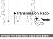
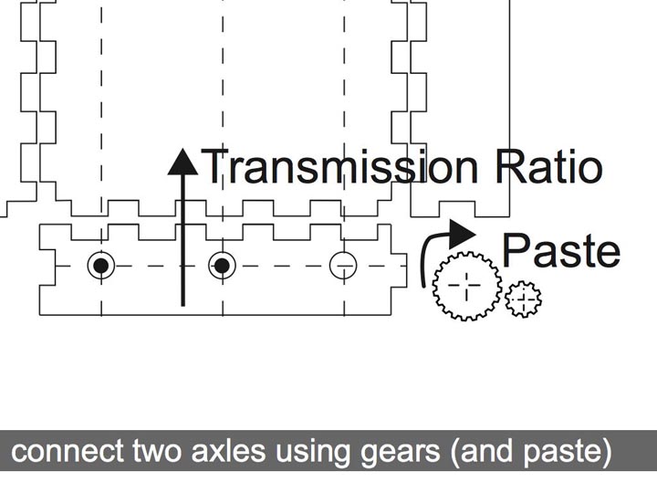
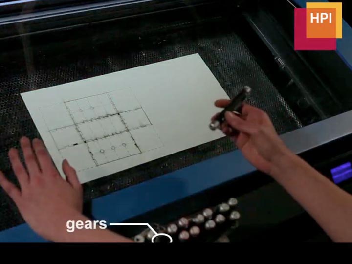
(d) We create the first pair of gears by selecting two axle holes, define the transmission ratio by marking the point where we want the two gears to meet, and show constructable where to create the gears using a cropmark. We create the second set of gears accordingly. (f) To create a wheel, we first create an axle hole using the hole tool. We then create a wheel around this axle hole using the scale tool. (g) We create a second wheel by copying the first one using the copy tool.
We are now done creating our parts. We remove them from the machine and assemble them, resulting in the vehicle shown in Figure 5.
The device is mechanically functional, because every mechanical connection was created using tools that embody appropriate constraints.
Figure 6: Interactively constructing the housing for the motorized vehicle and gearbox.
Figure 7 shows how we add gearbox and wheels. (a) To make sure that we end up with straight axles we draw three sketch lines using the polyline tool. (b) We create the first axle hole using the hole tool, the location of which snaps to the intersection of the two sketch lines located close by. (c) We draw all remaining axle holes using a single stroke concatenating multiple pigtails.
(d) We create the first pair of gears by selecting two axle holes, define the transmission ratio by marking the point where we want the two gears to meet, and show constructable where to create the gears using a cropmark. We create the second set of gears accordingly. (f) To create a wheel, we first create an axle hole using the hole tool. We then create a wheel around this axle hole using the scale tool. (g) We create a second wheel by copying the first one using the copy tool.
We are now done creating our parts. We remove them from the machine and assemble them, resulting in the vehicle shown in Figure 5.
The device is mechanically functional, because every mechanical connection was created using tools that embody appropriate constraints.
 Figure 7: Continuing the previous example, we add axles, a two-stage gearbox, and wheels.
Decorative functionality
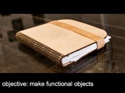
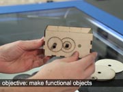
While constructable was designed with the goal of supporting interactive construction, its underlying concept of tools allows us to integrate form-giving (Figure 8) and decorative functionality as well (Figure 9).
Figure 7: Continuing the previous example, we add axles, a two-stage gearbox, and wheels.
Decorative functionality
While constructable was designed with the goal of supporting interactive construction, its underlying concept of tools allows us to integrate form-giving (Figure 8) and decorative functionality as well (Figure 9).
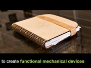
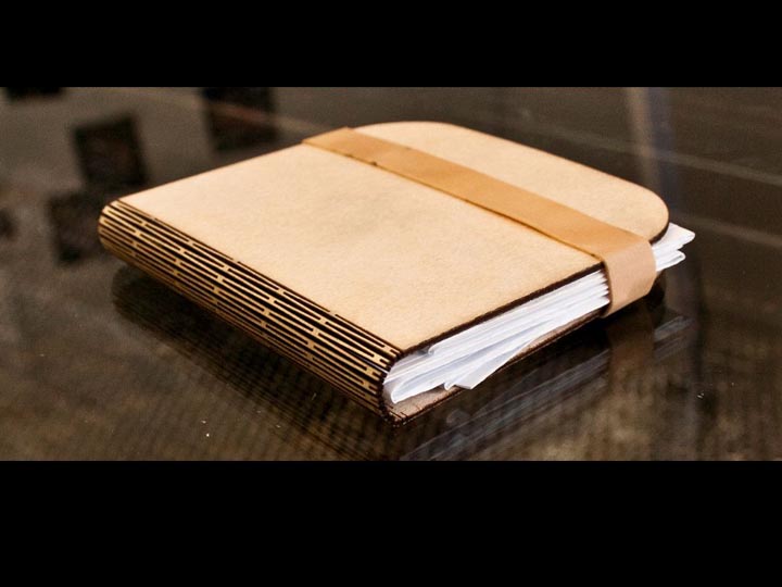
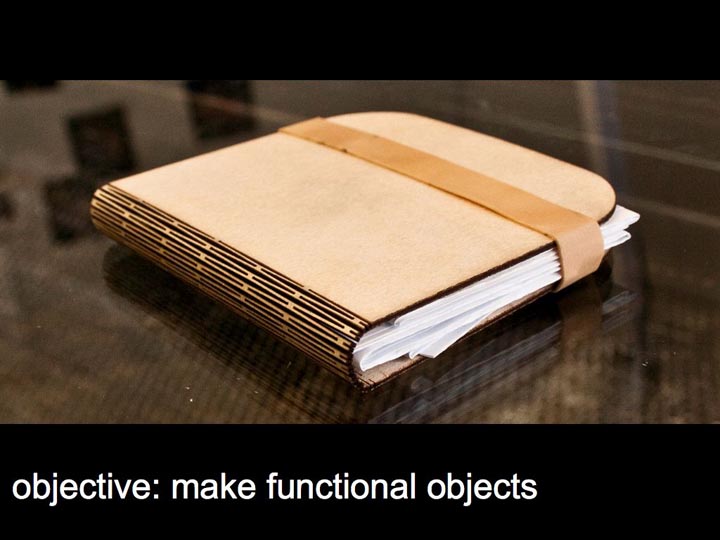
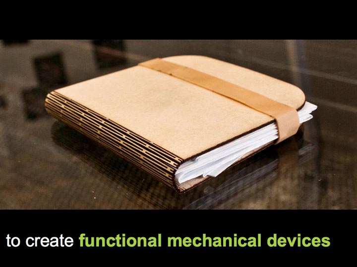
 Figure 8: Creating a wooden booklet sleeve by (a) drawing the cover with the polyline tool, then (b) smoothing the corners with the round tool, and (c) making the wood flexible using the bend tool [1].
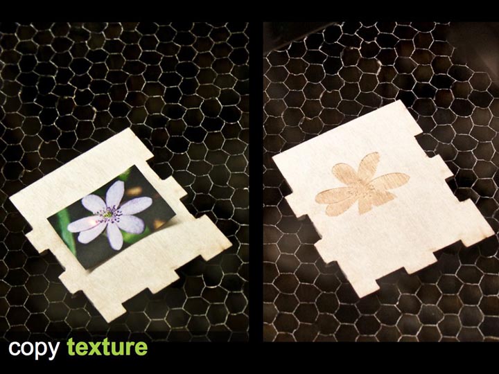
Figure 9 illustrates how we apply a logo to the housing of our motorized vehicle, á la CopyCAD [8]. (a) Continuing our earlier example, we place the housing of our motorized vehicle back into the machine, and position a photo with the desired logo on top of it. (b) We wave the rub-on tool across those areas of the photo that we want to transfer. (c) We take the photo back out, and as we close the lid, constructable engraves the logo into the housing.
Figure 8: Creating a wooden booklet sleeve by (a) drawing the cover with the polyline tool, then (b) smoothing the corners with the round tool, and (c) making the wood flexible using the bend tool [1].
Figure 9 illustrates how we apply a logo to the housing of our motorized vehicle, á la CopyCAD [8]. (a) Continuing our earlier example, we place the housing of our motorized vehicle back into the machine, and position a photo with the desired logo on top of it. (b) We wave the rub-on tool across those areas of the photo that we want to transfer. (c) We take the photo back out, and as we close the lid, constructable engraves the logo into the housing.
 Figure 9: Adding a decorative logo onto the side of the motorized vehicle using the rub-on tool.
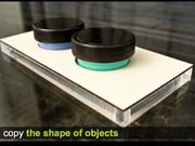
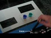
Similarly, the trace tool cuts the contours of a physical object into the workpiece. Figure 10 shows how to use this to create a holder for two paint jars.
Figure 9: Adding a decorative logo onto the side of the motorized vehicle using the rub-on tool.
Similarly, the trace tool cuts the contours of a physical object into the workpiece. Figure 10 shows how to use this to create a holder for two paint jars.
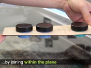
 Figure 10: Creating a holder for two paint jars by (a) selecting physical objects inside the cutter using the trace tool, (b) After removing the physical objects constructable cuts.
Finally, we can use the freehand tool to create unconstrained freehand lines and cuts (Figure 11).
Figure 10: Creating a holder for two paint jars by (a) selecting physical objects inside the cutter using the trace tool, (b) After removing the physical objects constructable cuts.
Finally, we can use the freehand tool to create unconstrained freehand lines and cuts (Figure 11).
 Figure 11: Sketching using the freehand tool.
Trial-and-error support using “undo” tools
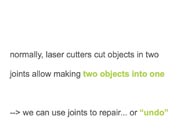
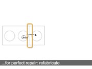
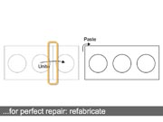
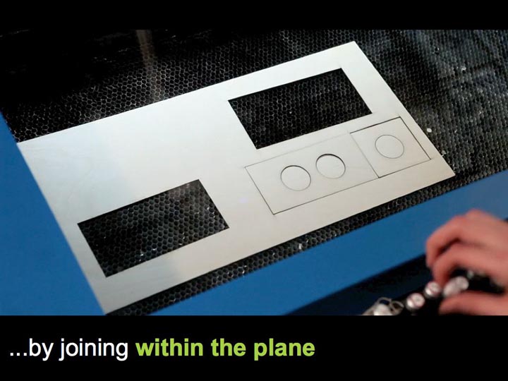
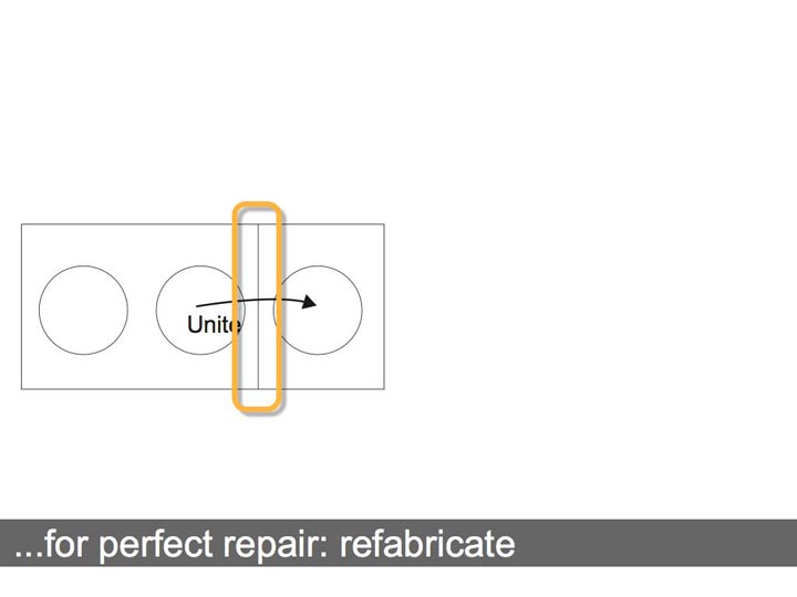
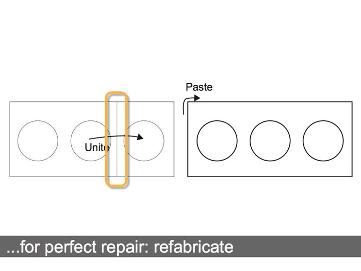
Finally, constructable offers basic support for trial-and- error by providing an approximation of “undo” tools. Since physical cuts cannot be undone, constructable’s “undo” tools instead refabricate the object — they create a copy that does not have the cut. Users apply the tool by crossing the cuts they want removed; they then paste the newly restored object.
While the primary purpose of the tool is to repair and undo, the way it achieves this is by uniting two objects and copy-ing the result. Since this functionality is useful beyond undo, we ended up giving the tool the name union tool.
In practice, any tool that unites two objects can be used as an undo tool. Figure 12 shows the butterfly joint tool, which connects two objects using a butterfly connector. This tool produces a butterfly-shaped hole across the cut and lets users paste a matching butterfly-shaped connector. Users repair the cut on assembly by placing the connector into the hole—it sits tight enough to create a lasting connection. While the union tool obviously creates the stronger connection, a butterfly joint consumes less material.
Figure 11: Sketching using the freehand tool.
Trial-and-error support using “undo” tools
Finally, constructable offers basic support for trial-and- error by providing an approximation of “undo” tools. Since physical cuts cannot be undone, constructable’s “undo” tools instead refabricate the object — they create a copy that does not have the cut. Users apply the tool by crossing the cuts they want removed; they then paste the newly restored object.
While the primary purpose of the tool is to repair and undo, the way it achieves this is by uniting two objects and copy-ing the result. Since this functionality is useful beyond undo, we ended up giving the tool the name union tool.
In practice, any tool that unites two objects can be used as an undo tool. Figure 12 shows the butterfly joint tool, which connects two objects using a butterfly connector. This tool produces a butterfly-shaped hole across the cut and lets users paste a matching butterfly-shaped connector. Users repair the cut on assembly by placing the connector into the hole—it sits tight enough to create a lasting connection. While the union tool obviously creates the stronger connection, a butterfly joint consumes less material.
 Figure 12: Undoing a cut by re-uniting the pieces using the butterfly tool.
Benefits and Limitations, Summary of the Design
In the above walkthrough, we demonstrated interactive construction using constructable. We showed how constructable allows to interactively construct a functional mechanical device by bringing some of the key qualities of CAD-based personal fabrication into interactive fabrication.
Precise input and output
Constructable achieves the precision required to make functional mechanical devices as follows:
Precise input: Even though all input to constructable is mediated through a hand-held tool, the resulting jerkiness never interfered with precision because all relevant parame- ters are appropriately constrained. Only parameters with no functional implications, such as the size of the base of the motorized vehicle, were defined free hand.
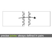
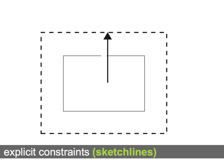
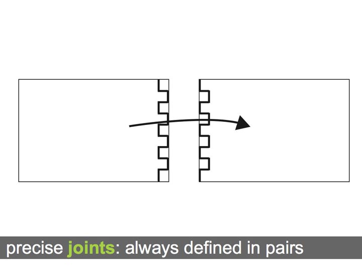
Constructable uses three types of constraints: (1) Each tool implements constraints; the polyline tool, for example, draws only rectilinear contents. (2) Sketch lines allow users to add constraints explicitly. (3) A special class of tools that create connections, such as finger joints create both halves of the connection at once. As a result, finger joints always fit perfectly even though they involve two parts. The gear tool is based on the same concept and one might say that it connects two axles.
Precise output: As mentioned earlier, all tools explain themselves exclusively through the cut or sketch line they produce. Since this allows all output to be created using the laser cutter itself, constructable’s geometry output is extremely precise. This offers orders of magnitude higher resolution than projection and is never subject to calibration issues.
No projection
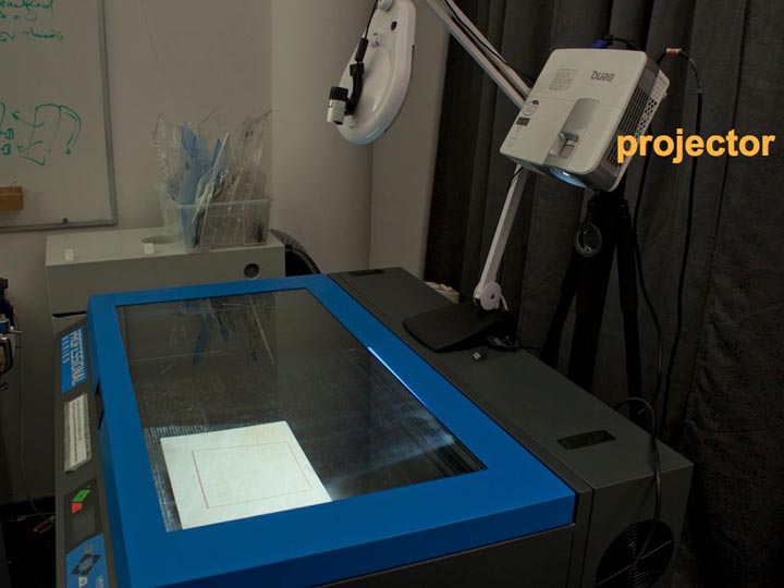
An early version of our system did feature a projector, similar to several systems in the related work, such as CopyCAD [8]. Letting go of it not only increased precision, but also made sure we directed users’ attention at the work-piece at all times, rather than at a projection collocated with the workpiece.
A side effect of not having a computer display meant that we had to eliminate all hidden state and modes, because there was no way to keep users informed about them. This led us to design the proxy laser model, in which the current set of constraints is represented solely by which physical device the user is currently holding.
As another side effect of using the cutter as the sole visual feedback device, sketch lines became permanent. While users can erase sketch lines by replicating the final object using the unite tool, we think that users will typically choose to leave these lines in, the same way that designers leave sketch lines in to illustrate their process or even because they are esthetically pleasing [4].
Trial-and-error using “undo” tools
We implemented trial-and-error using special “undo” functions, such as the union and butterfly joint tool that allow users to re-create the previous state of an object by refabricating it.
Fast interaction via the proxy laser mechanism
As mentioned earlier, constructable achieves fast interaction using the proxy laser mechanism, i.e., drawing with low-power laser tools, the effect of which is implemented by a high-power cutting laser. We found the resulting interaction to invite a powerful conceptual model, namely that the cutting laser amplifies the proxy laser, similar to how power brakes and power steering amplify the driver’s muscle strength. We plan to develop this notion further in future versions of constructable, with the ultimate goal of causing at least the freehand proxy laser to invite the interpretation that it itself is cutting.
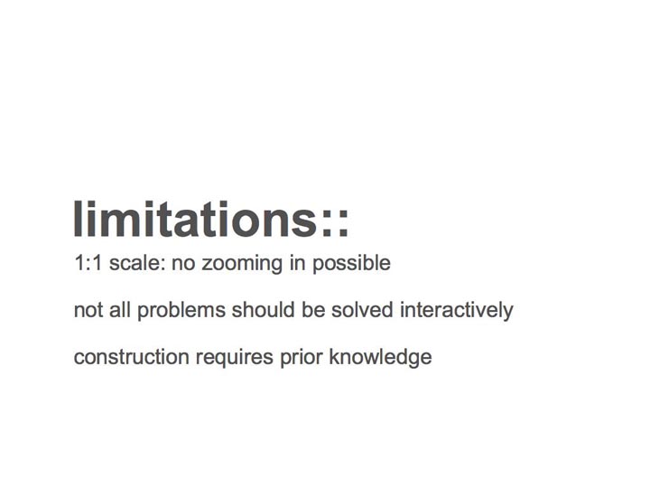
Limitations
Like any tool, constructable is useful for some design problems and less so for others. While constructable extends the range of problems that can be tackled interactively, it is obviously not a CAD system. As with traditional wood-working tools, some types of projects can be tackled tool-in-hand, while more advanced problems require users to sit down with a piece of paper first. The same way that saw and wood chisel cannot replace a detailed design process, constructable cannot replace CAD.
Another limitation is that all construction with constructable is inherently scale 1:1 and constructable offers no way of inspecting a detail in magnification. Similar to working with traditional woodworking tools, this limits users to projects that fit a particular scale.
Finally, constructable was not designed with walk-up use in mind. While some tools, such as the finger joint tool have the potential to make complex construction elements accessible to inexperienced users, mechanical construction in general does require know-how. Rather than addressing first time users, we designed the majority of constructable’s tools so as to be generic in nature, to apply to each other, and thereby allow for a wide range of constructions.
Ergonomic: The Drafting Table Form Factor
While constructable is primarily about constructive functionality, we made some observations on ergonomics.
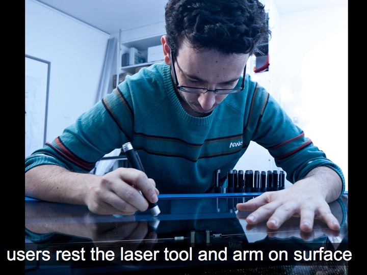
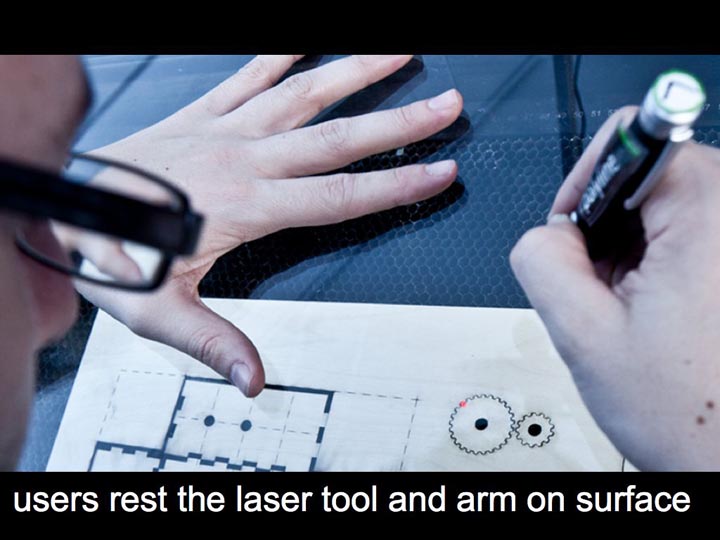
While we initially perceived it mostly as a design hurdle, the laser cutter’s glass cover turned out to become one of the key elements creating the affordance of our system. (Figure 13a). By allowing users to rest their body weight on the glass, it allows users to get even closer to the workpiece without worrying about interfering with it. Furthermore, we found ourselves resting proxy lasers on the glass while drawing (Figure 13b), which adds substantial stability, making the interaction even more precise.
Figure 12: Undoing a cut by re-uniting the pieces using the butterfly tool.
Benefits and Limitations, Summary of the Design
In the above walkthrough, we demonstrated interactive construction using constructable. We showed how constructable allows to interactively construct a functional mechanical device by bringing some of the key qualities of CAD-based personal fabrication into interactive fabrication.
Precise input and output
Constructable achieves the precision required to make functional mechanical devices as follows:
Precise input: Even though all input to constructable is mediated through a hand-held tool, the resulting jerkiness never interfered with precision because all relevant parame- ters are appropriately constrained. Only parameters with no functional implications, such as the size of the base of the motorized vehicle, were defined free hand.
Constructable uses three types of constraints: (1) Each tool implements constraints; the polyline tool, for example, draws only rectilinear contents. (2) Sketch lines allow users to add constraints explicitly. (3) A special class of tools that create connections, such as finger joints create both halves of the connection at once. As a result, finger joints always fit perfectly even though they involve two parts. The gear tool is based on the same concept and one might say that it connects two axles.
Precise output: As mentioned earlier, all tools explain themselves exclusively through the cut or sketch line they produce. Since this allows all output to be created using the laser cutter itself, constructable’s geometry output is extremely precise. This offers orders of magnitude higher resolution than projection and is never subject to calibration issues.
No projection
An early version of our system did feature a projector, similar to several systems in the related work, such as CopyCAD [8]. Letting go of it not only increased precision, but also made sure we directed users’ attention at the work-piece at all times, rather than at a projection collocated with the workpiece.
A side effect of not having a computer display meant that we had to eliminate all hidden state and modes, because there was no way to keep users informed about them. This led us to design the proxy laser model, in which the current set of constraints is represented solely by which physical device the user is currently holding.
As another side effect of using the cutter as the sole visual feedback device, sketch lines became permanent. While users can erase sketch lines by replicating the final object using the unite tool, we think that users will typically choose to leave these lines in, the same way that designers leave sketch lines in to illustrate their process or even because they are esthetically pleasing [4].
Trial-and-error using “undo” tools
We implemented trial-and-error using special “undo” functions, such as the union and butterfly joint tool that allow users to re-create the previous state of an object by refabricating it.
Fast interaction via the proxy laser mechanism
As mentioned earlier, constructable achieves fast interaction using the proxy laser mechanism, i.e., drawing with low-power laser tools, the effect of which is implemented by a high-power cutting laser. We found the resulting interaction to invite a powerful conceptual model, namely that the cutting laser amplifies the proxy laser, similar to how power brakes and power steering amplify the driver’s muscle strength. We plan to develop this notion further in future versions of constructable, with the ultimate goal of causing at least the freehand proxy laser to invite the interpretation that it itself is cutting.
Limitations
Like any tool, constructable is useful for some design problems and less so for others. While constructable extends the range of problems that can be tackled interactively, it is obviously not a CAD system. As with traditional wood-working tools, some types of projects can be tackled tool-in-hand, while more advanced problems require users to sit down with a piece of paper first. The same way that saw and wood chisel cannot replace a detailed design process, constructable cannot replace CAD.
Another limitation is that all construction with constructable is inherently scale 1:1 and constructable offers no way of inspecting a detail in magnification. Similar to working with traditional woodworking tools, this limits users to projects that fit a particular scale.
Finally, constructable was not designed with walk-up use in mind. While some tools, such as the finger joint tool have the potential to make complex construction elements accessible to inexperienced users, mechanical construction in general does require know-how. Rather than addressing first time users, we designed the majority of constructable’s tools so as to be generic in nature, to apply to each other, and thereby allow for a wide range of constructions.
Ergonomic: The Drafting Table Form Factor
While constructable is primarily about constructive functionality, we made some observations on ergonomics.
While we initially perceived it mostly as a design hurdle, the laser cutter’s glass cover turned out to become one of the key elements creating the affordance of our system. (Figure 13a). By allowing users to rest their body weight on the glass, it allows users to get even closer to the workpiece without worrying about interfering with it. Furthermore, we found ourselves resting proxy lasers on the glass while drawing (Figure 13b), which adds substantial stability, making the interaction even more precise.
 Figure 13: (a) The glass cover supports users’ weight, allowing them to get close to the workpiece. (b) Resting proxy lasers onto the glass allows for precise interaction.
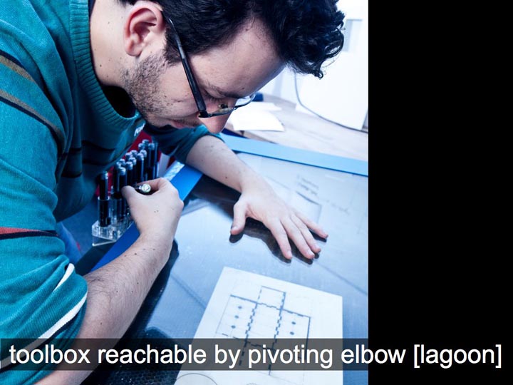
To invite this interpretation and posture, we positioned the proxy laser tools as shown in Figure 13c. This allows users to reach tools without lifting their arm, but instead pivoting around their elbows similar to the Lagoon in Alias Sketchbook [6].
We found all of the above to invite the interpretation of constructable as a drafting table, the “drawing” on which is the actual physical object itself. We plan on building on this interpretation in future versions by tilting the glass cover slightly towards the user (e.g., as in ActiveDesk [7]).
Contribution
The main contribution of this paper is the concept of interactive construction, which we support with the functional system prototype constructable. Our demo scenarios illustrate how users can create functional mechanical devices, which exceeds the complexity of examples created in the interactive fabrication literature. We are thus primarily making a systems contribution.
In addition, our system contains a series of novel elements, including (a) the proxy laser mechanism, i.e., drawing with low-power laser tools, the effect of which is implemented by a high-power cutting laser, (b) the use of the laser cutter as a super high precision display, replacing projection, and (c) the notion of undoing a physically destructive action by refabricating the broken piece.
Implementation
Figure 14 shows how constructable processes proxy laser input in order to generate cutting laser output.
Figure 13: (a) The glass cover supports users’ weight, allowing them to get close to the workpiece. (b) Resting proxy lasers onto the glass allows for precise interaction.
To invite this interpretation and posture, we positioned the proxy laser tools as shown in Figure 13c. This allows users to reach tools without lifting their arm, but instead pivoting around their elbows similar to the Lagoon in Alias Sketchbook [6].
We found all of the above to invite the interpretation of constructable as a drafting table, the “drawing” on which is the actual physical object itself. We plan on building on this interpretation in future versions by tilting the glass cover slightly towards the user (e.g., as in ActiveDesk [7]).
Contribution
The main contribution of this paper is the concept of interactive construction, which we support with the functional system prototype constructable. Our demo scenarios illustrate how users can create functional mechanical devices, which exceeds the complexity of examples created in the interactive fabrication literature. We are thus primarily making a systems contribution.
In addition, our system contains a series of novel elements, including (a) the proxy laser mechanism, i.e., drawing with low-power laser tools, the effect of which is implemented by a high-power cutting laser, (b) the use of the laser cutter as a super high precision display, replacing projection, and (c) the notion of undoing a physically destructive action by refabricating the broken piece.
Implementation
Figure 14 shows how constructable processes proxy laser input in order to generate cutting laser output.
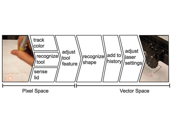
 Figure 14: Data processing flow in constructable.
Sensing
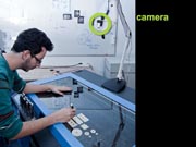
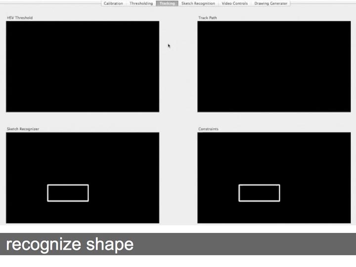
Constructable observes the workpiece using a web cam (MS Lifecam, 844x448px, 30 fps) and extracts the dot produced by the proxy-lasers using color tracking. Constructable then smoothes tool paths using a Kalman Filter and performs shape recognition on paths using PaleoSketch [25] before applying the geometric operations and spatial constraints defined by the tool.
At this point, constructable records the interaction history, which it uses to support undo and selective repairs using the union tool.
Output to the laser cutter
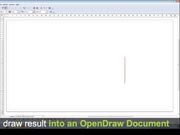
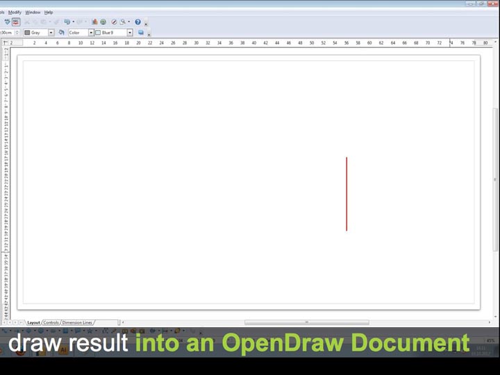
Constructable now outputs the shape to the laser cutter, currently a Universal PLS6.150D. Using the OpenDraw API, Constructable draws the shape into an OpenDraw document, which it sends to the cutter using the printer interface. As required by Universal laser cutter systems, constructable encodes the necessary meta-information into the color of the respective line, i.e., cutting-depth (mm), laser power (percentage), and speed (percentage). A red 0pt line, for example, causes the laser to cut, while green is used to create a shallow, low-power sketch line. Constructable sends all communication using the Open Sound Protocol, which makes it easy to adapt the system to other hardware components, such as a different laser cutter model.
Remixing: using physical objects as a reference
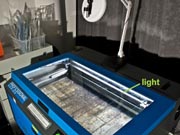
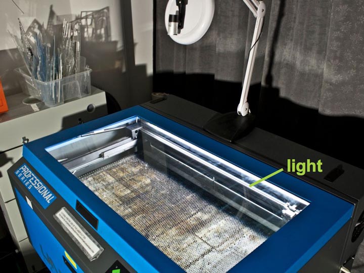
Constructable captures physical objects using the same camera that tracks the laser dots. A bar of fluorescent light mounted inside the cutter supports this by providing homogeneous, reflection-free illumination of the workpiece. An IR rangefinder sensor informs the system when the lid is open.
Proxy lasers
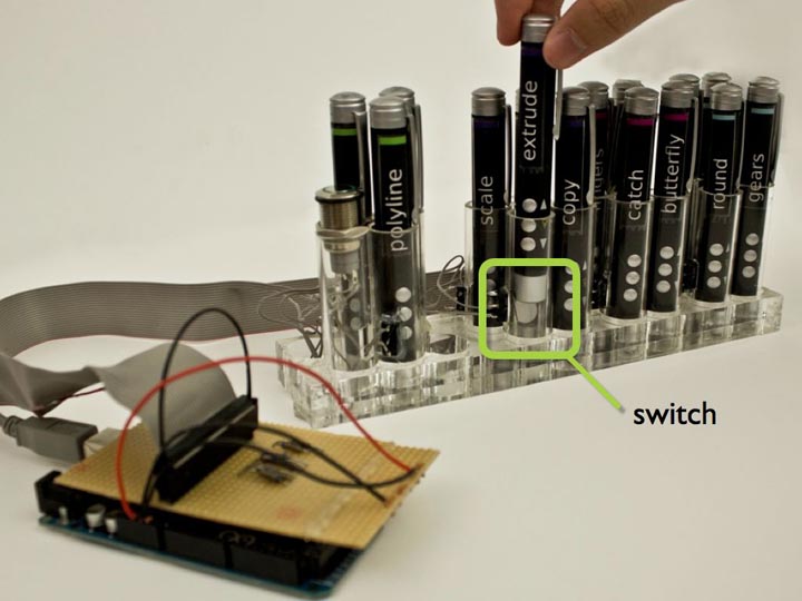
In order to retrieve the constraint set represented by the current tool, constructable determines which tool is in use using mechanical switches, one of which is installed in each tool holder (similar to pen “recognition” in SmartBoards, smarttech.com). This bypass allows us to implement all proxy lasers using a single type of off-the-shelf laser pointer. The buttons on all proxy lasers trigger an IR signal, which Constructable monitors using an IR receiver placed next to the camera.
Similar to the tracking button, the cut and sketch line buttons are spring-loaded in order to eliminate mode errors [13]. Users operate them without letting go of the tracking button, which users perform by rocking their finger back and forth between tracking button and the center position of tracking and cut button. For optimized ergonomics during prolonged use [13] constructable offers a dual-footswitch pedal, which is fulfilling the same purpose as the cut and sketch line barrel buttons.
Conclusion
In this paper, we proposed interactive construction as a way to enable users to interactively create functional mechanical devices. Our prototype called constructable serves as a drafting table that produces physical output in every step. By building constraints into tools, providing sketch lines and by using the laser cutter itself for high precision output, constructable offers the necessary precision required to produce simple, yet functional mechanics that cannot be created with traditional interactive fabrication tools. Equally important, constructable allows for fast fabrication by making a high-power cutting laser accessible to the user via safe low-power proxy lasers. As future work, we plan to extend constructable to allow for collaborative use.
Demos at CHI'13 and TEI'13
Figure 14: Data processing flow in constructable.
Sensing
Constructable observes the workpiece using a web cam (MS Lifecam, 844x448px, 30 fps) and extracts the dot produced by the proxy-lasers using color tracking. Constructable then smoothes tool paths using a Kalman Filter and performs shape recognition on paths using PaleoSketch [25] before applying the geometric operations and spatial constraints defined by the tool.
At this point, constructable records the interaction history, which it uses to support undo and selective repairs using the union tool.
Output to the laser cutter
Constructable now outputs the shape to the laser cutter, currently a Universal PLS6.150D. Using the OpenDraw API, Constructable draws the shape into an OpenDraw document, which it sends to the cutter using the printer interface. As required by Universal laser cutter systems, constructable encodes the necessary meta-information into the color of the respective line, i.e., cutting-depth (mm), laser power (percentage), and speed (percentage). A red 0pt line, for example, causes the laser to cut, while green is used to create a shallow, low-power sketch line. Constructable sends all communication using the Open Sound Protocol, which makes it easy to adapt the system to other hardware components, such as a different laser cutter model.
Remixing: using physical objects as a reference
Constructable captures physical objects using the same camera that tracks the laser dots. A bar of fluorescent light mounted inside the cutter supports this by providing homogeneous, reflection-free illumination of the workpiece. An IR rangefinder sensor informs the system when the lid is open.
Proxy lasers
In order to retrieve the constraint set represented by the current tool, constructable determines which tool is in use using mechanical switches, one of which is installed in each tool holder (similar to pen “recognition” in SmartBoards, smarttech.com). This bypass allows us to implement all proxy lasers using a single type of off-the-shelf laser pointer. The buttons on all proxy lasers trigger an IR signal, which Constructable monitors using an IR receiver placed next to the camera.
Similar to the tracking button, the cut and sketch line buttons are spring-loaded in order to eliminate mode errors [13]. Users operate them without letting go of the tracking button, which users perform by rocking their finger back and forth between tracking button and the center position of tracking and cut button. For optimized ergonomics during prolonged use [13] constructable offers a dual-footswitch pedal, which is fulfilling the same purpose as the cut and sketch line barrel buttons.
Conclusion
In this paper, we proposed interactive construction as a way to enable users to interactively create functional mechanical devices. Our prototype called constructable serves as a drafting table that produces physical output in every step. By building constraints into tools, providing sketch lines and by using the laser cutter itself for high precision output, constructable offers the necessary precision required to produce simple, yet functional mechanics that cannot be created with traditional interactive fabrication tools. Equally important, constructable allows for fast fabrication by making a high-power cutting laser accessible to the user via safe low-power proxy lasers. As future work, we plan to extend constructable to allow for collaborative use.
Demos at CHI'13 and TEI'13
Packing at Hasso Plattner Institute, Berlin, Germany


 Unpacking in Barcelona


 Demo Setup


 Demo
Demo


